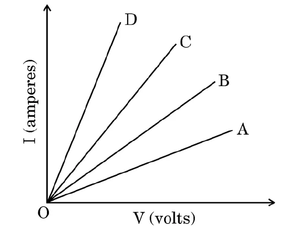
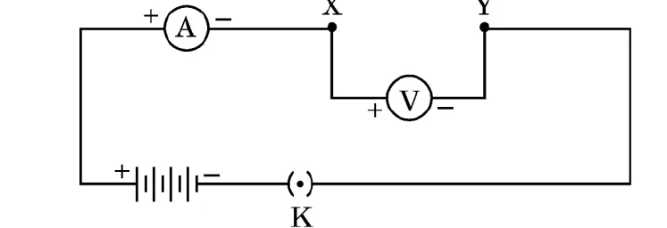
Case study 3. As shown in the diagram, an electric circuit consisting of an ammeter, a voltmeter, 4 cells of 1.5 V each, a plug key with a gap XY was set up. Voltmeter and ammeter readings were recorded in the observation table for four arrangements: No. 1, only resistor R₁ in gap XY; No. 2, only resistor R₂; No. 3, R₁ and R₂ in series; No. 4, R₁ and R₂ in parallel. Based on the observations, four V–I graphs A, B, C and D as shown in figure were drawn (current I on the vertical axis, voltage V on the horizontal axis; D is the steepest line and A the least steep).
(a) Which one of the graphs represents the series combination of R₁ and R₂? [1]
(b) Which one of these graphs represents the parallel combination of R₁ and R₂? [1]
(c) (i) Show an arrangement of three resistors, each of resistance 10 Ω, so that the combination has a resistance of 15 Ω. Give justification for your answer. [2]
OR
(c) (ii) A battery of 6 V is connected with a series combination of five resistors of 0.1 Ω, 0.2 Ω, 0.3 Ω, 0.4 Ω and 0.5 Ω. How much current would flow through the 0.3 Ω resistor? Justify your answer. [2]